25+ microwave communication system block diagram
The figure shows a block schematic of the essential parts of a digital communication system. The practical PCM system use 8 bit code.
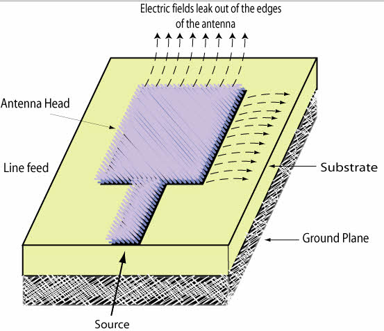
Introduction To Types Of Microwave Antennas In Communication Systems
The block diagram description is.
. It is intended for scholars in the field of electronics and communication engineering. Radio waves travel near the surface of the earth and also radiate skyward at various angles to the. Sreekanth - 2003 Digital Microwave Communication - George Kizer - 2013-06-24 The first book to cover all engineering.
The towers used for Microwave Link in Electronic Communication range in height up to about 25 m depending on the terrain length of that particular link and location of the tower itself. Communications System Diagram 2 FlynnKatz - SDR July 1 2010 Information Source and Input Transducer. Microwaves are electromagnetic waves EM in the frequency range from 300MHz up to 300GHz which corresponds to wavelengths from 1mm to 1m Pozar 2005.
5 LINE CODING-- The binary signal with its DC component is unsuitable for its transmission on transformer and AC coupled transmission. 25 FlynnKatz - SDR July 1. In this paper we present the design and implementation of a new software tool for mobile-phone network planning.
5 is a block diagram of one embodiment of a converted analog radio indicated. Digital Microwave Communication Systems - PV. Block Diagram of Complete Radio Receiver.
Includes relevant diagrams and solved problems. 11 Protected Microwave Radio Link Block Diagram Link Block Diagram This diagram is from an NEC 500 series microwave link system circa 1983 and shows one. 1 is a block diagram of a microwave communication system having a number of microwave hops.
They are part of radio. The Microwave Devices are used for each system as shown in Figure 1. Schematic representation of a link is shown in Fig.
Microwave Line of Sight Link Engineering Pablo. At the transmitter side of the link three streams of data are directed to the three microwave transmitters. This catalog explains the Microwave devices by each Microwave block diagram for the application system.
The communication links are. Block Diagram Of Microwave Communication System - Read Block Diagram Of Microwave Communication System PDF on your Android iPhone iPad or PC directly the.
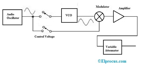
Signal Generator Circuit Working Types And Its Applications

Blocking Microwave Signals Electromagnetic Radiation Us Department Of Justice Emf
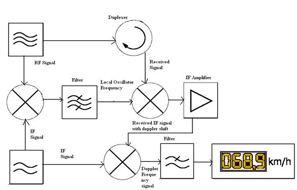
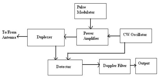
Radar Basics Types Working Range Equation Its Applications

Radar Basics Types Working Range Equation Its Applications Phase Detector Planetary System Remote Sensing
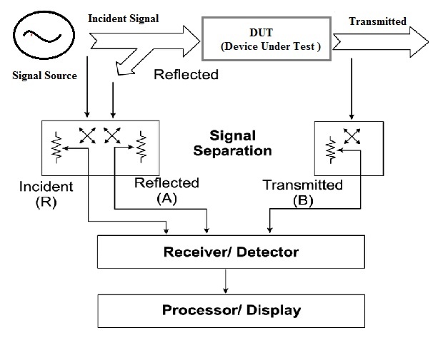
Network Analyzer Block Diagram Types Working Its Applications
![]()
Wireless Power Transmission Through Solar Power System Working

Transmitter Receiver An Overview Sciencedirect Topics

48 Volt Starter Generator
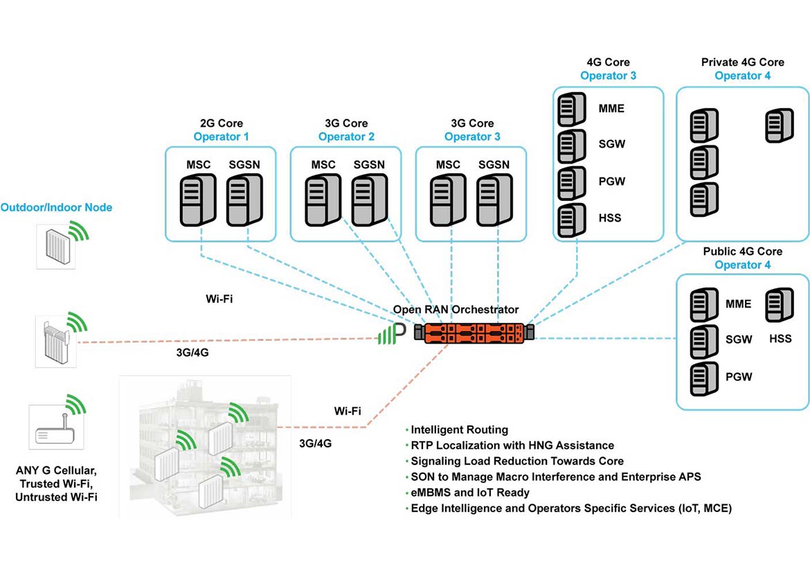
Multi Operator Core Networks Mocn Parallel Wireless

Generic Block Diagram Of A Wireless Power System Circuit Projects Wireless Power
Would A New Microwave Oven Be Safer And More Energy Efficient Than One That Is 10 Years Old Quora

Transmitter Receiver An Overview Sciencedirect Topics

Block Diagram Of Modulated Ir Transmission And Reception Block Diagram Communication Networks Diagram
Radar Basics Types Working Range Equation Its Applications
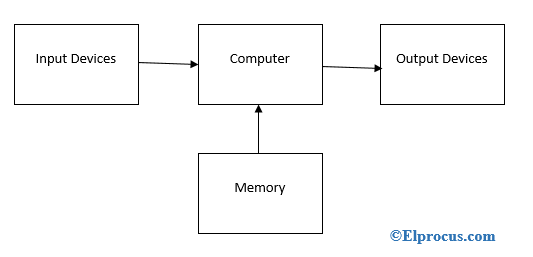
Embedded Operating System Block Diagram And Differences
2
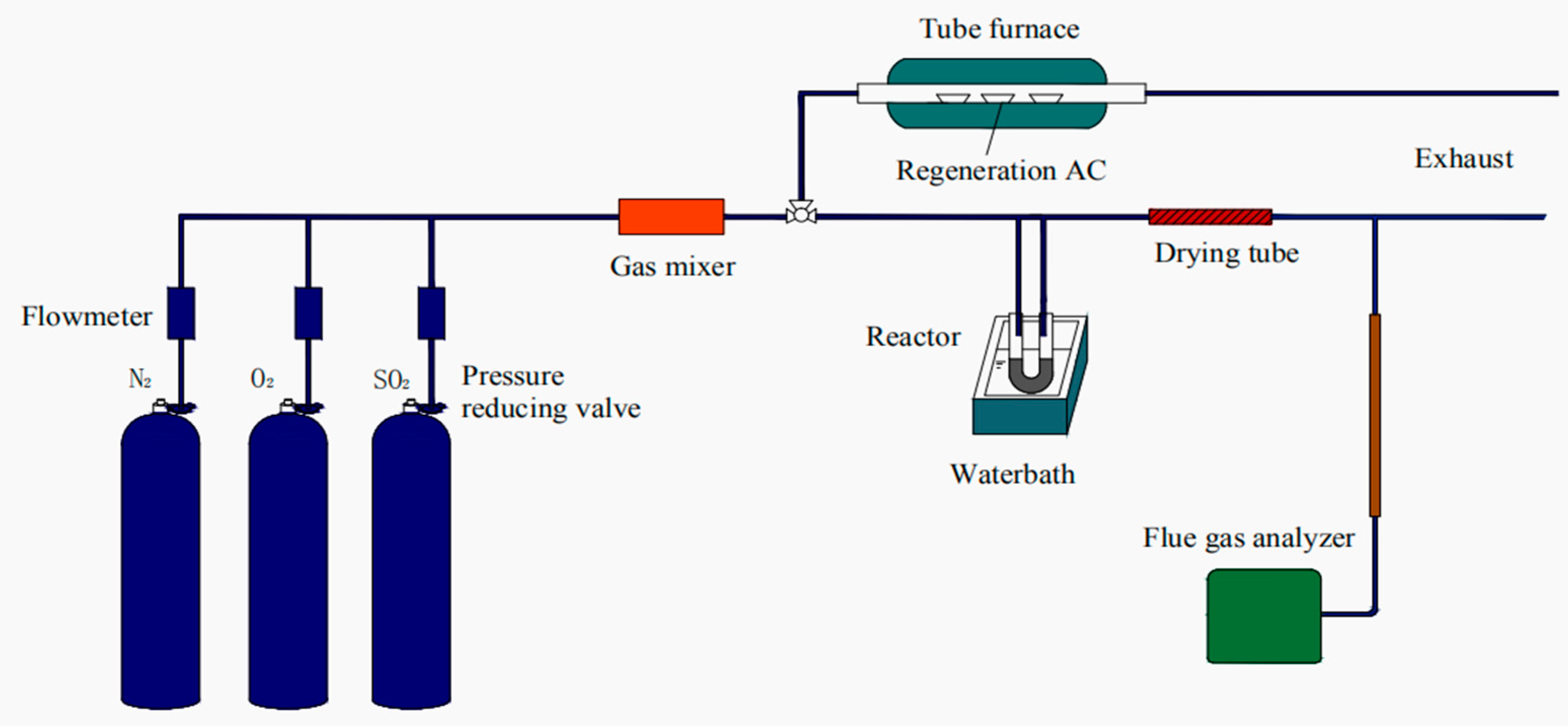
Applied Sciences Free Full Text Regeneration Performance Of Activated Carbon For Desulfurization Html